 April 18, 2018
|
||||
What Are You Looking Forward
|
||||
|
 ABC's of VFD's Installation Need to Know (Part 1)
by Paul Figie, Application Engineer, EZAutomation
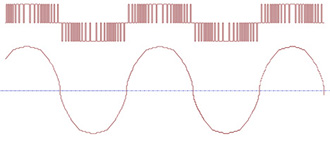
Most VFD’s today take advantage of high speed microprocessors to create the waveform output necessary to drive the motor being controlled. This is accomplished by switching outputs on and off at varying duty cycles called Pulse Width Modulation or PWM. The speed or frequency at which output is switched must be much greater than the frequency of the waveform that is being created this is called the modulation or carrier frequency. Depending on the output device configuration used in this switch process the carrier frequencies are generally between 1-20 KHz. The figure below gives an example of the microprocessor generated PWM and the waveform it creates.
Generating PWM signals to control varying output frequencies has become very practical with the advancement of today’s Microprocessors. Microprocessor Controlled VFD’s have become very sophisticated in their control capabilities but not without some drawbacks. The high speed switching to create the output to the Motor generates Electromagnetic Interference (EMI). This EMI noise is inherent to all VFD’s using PWM and can be extremely problematic in your control system if extra steps are not taken to minimize it. Proper VFD installation is extremely important not only for the VFD and motor but also all other electrical devices in you control system. Improper VFD installation can not only cause damage to your motor and drive, but could cause erratic unpredictable and potentially dangerous conditions to surrounding electrical control devices.
1. VFD - Read the VFD Manufactures Drive Installation procedures. Pay close attention and follow all of the recommendations. This should include:
- a. VFD Mounting requirements to maintain proper heat dissipation and Electrical Noise isolation.
- b. Proper VFD and Motor grounding procedures.
- c. Motor wiring (Type of wire and method of routing) Metallic shielded with non-Metallic armored motor runs that are single point grounded on the VFD side are usually specified
- d. Allowable wire distance from the VFD to the Motor
- e. When the use of Line Reactors or Load Reactors may be required
- f. Motor overload protection for your specific motor and application.
- g. Your VFD should be in a separate enclosure from your PLC, HMI or other controls
2. Motor - Use Inverter Duty Motor type. Check that you are not exceeding manufactures performance recommendations.
- a. Note: not all Inverter duty motors are created equal. EMI noise within Induction motors has been known to induce currents on the rotor shaft that conduct through the motor bearings causing premature bearing failure. Some Motor manufactures insulate the bearing on one side of the rotor to alleviate this condition. EMI noise can cause voltage spikes within the motor that can break down its insulation within windings so higher insulation ratings are required.
- b. When mounting the Motor be sure the paint on the surfaces of the motor and the equipment it is mounted on is removed. This will allow a good electrical ground path.
3. Surrounding Equipment - VFD’s not only transmit electrical noise in proximity to the drive itself but also along the wiring run to the motor.
- a. Take extra care not to run any control signal wiring or communication wiring near your VFD, VFD Motor wire Runs or VFD Power runs. Running control or communication wiring in a parallel path to VFD runs can cause intermittent and erratic problems to other electric/electronic components that my not even be in proximity or related to your control system.
- b. VFD’s can reflect noise back into the sourcing power lines and should have a separate power source from any other control devices
- c. Be sure to follow all applicable electrical wiring codes and safe wiring practices
- i. NEC “National Electric Code”
- ii. IEC/EN 61800-3 “Adjustable Speed Electrical Power Drive“
- iii. NEMA Standards Publication ICS 7.1-2000 “Safety Standards for Construction and Guide for Selection, Installation, and Operation of Adjustable-Speed Drive Systems
To make your VFD Drive installation successful upfront planning is key. Research and planning of your control system is always save time well spent.
Previous Articles of Interest:
ABC's of VFD's and Motor Selection (Part 1)
Servo Motors - What They Are and How They Work
Connect With Us:
| YouTube |
Featured Product

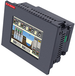
HMI Features:
- 5.7", 7" (Wide), 8", 10.4" TFT Color Touchscreens
- Built in Image Library (4000+ Symbols)
- Advanced Alarm Messages & Screens
- Email & Text Message Alerts
- Trending Graphs
- Data logging
- Up to 999 User designed screens
PLC Features:
- Flexible I/O (Digital, Analog, High speed counters, Temperature, PWM)
- Auto-tune PID, up to 8 independent loops
- Advanced Math Function Blocks
- Recipe Editing
- Date, Time and Event Based Control
- RS232/422/485 Expansion port (up to 2048 I/O)

![]()
Advanced Processing Technology (AvPro) has innovated composite process control and measurement technologies for more than 25 years. Focusing much effort toward the study of advanced sensors, as well as software controls, AvPro has helped manufacturing companies such as Boeing, General Atomics and Spirit Aerosystems measure and control structural composites manufacturing.
405-360-4848
Chad Hughes
chughes@avproinc.com
AVPro, Inc.
![]() EZRack PLC Torture Test »
EZRack PLC Torture Test »
We "turn the screws" on the EZRack PLC and the results are impressive!
 EZTouch Fully Loaded, Fully American, Fully Reliable »
EZTouch, rated Best HMI 5 to 1 still gives them a run for their money.

Life and Safety critical electrical control circuits, such as E-Stops, should not depend serial or any other network connections to function. Should a network fail or become disconnected human safety would be at risk. OSHA 29 CFR 1910.179 (a)(59) defines "emergency stop switch"
 "I have half a mind to get off Facebook, but having half a mind is how I ended up on there to begin with."
About EZAutomation
Serving the Automation industry for 50 years.
EZAutomation proudly designs, engineers and manufactures our automation products in Bettendorf, IA. It's your one stop shop for all your automation needs: HMIs, PLCs, smart LED displays, timers, Proximity sensors, power supplies and much more.
Phone: 877-774-3279
4140 Utica Ridge Rd.
Bettendorf, IA 52722
Email: Support | Sales