ABC's of VFD's and Motor Selection (Part 1)
by Paul Figie, Application Engineer, EZAutomation
VFD’s … How they work
VFD’s Variable Frequency Drives are capable of generating a 3phase output to drive motors at other frequencies than standard 60Hz. This provides a very effective way to control not only a motors speed, but also allows ramping of startup and stopping and more. Variable Frequency Drives in most types convert an AC power source to DC and then use it to regenerate 3Phase AC at the desired frequency Most VFD’s Integrate microprocessors within the VFD’s to calculate Voltage/Frequency curves based on motor parameters settings. This also allows different control algorithms to be incorporated depending on the required application.
Voltage Speed Relationship: AC induction motors act like inductors. And with inductors as the frequency applied to them decreases the natural saturation voltage decreases and as the frequency increases the voltage increases. That is why VFD’s are usually are setup to compensate the voltage for the frequency they are outputting. A volts per hertz curve is used in the control calculations.
Flux Vector Control: Open Loop/Close Loop; Constant Torque/Variable Torque: All of these terms describe the types of processing used in the motor control. Here is a breakdown to simplify how each works to help with selection and application of how the motor will respond to the way it will be used.
First you must determine why the speed is going to be controlled. In applications such as fans, blowers and centrifugal pumps. The pump or blower volume or flow output is the process variable that is to be controlled. This would be considered a Variable Torque application where optimizing motor torque is considered for total efficiency with output flow or volume. The complete calculations optimize frequency, voltage and current to maintain the motor speed & torque for the desired flow output. The implementation of Flux Vector Control is the means of determining the real time internal motor magnetic flux characteristics. This is calculated within the VFD’s internal microprocessor. By calculating instantaneous voltage current vector relationship with in the motor, the basic Volts per hertz is further modified for better optimization. Applications like Positive displacement pumps, Conveyors, Hoists, Compressors and other direct mechanical driven actuations are considered Constant Torque. With the use of a VFD in conjunction with a PLC having additional Motor feedback, extremely accurate Close Loop control can be obtained.
Speed Ramp: By using a ramp up frequency to start motors the electrical inrush current can be significantly reduced saving on you electrical system. Ramp up also can help with the mechanical longevity of the equipment. By using the frequency to ramp down the mechanical operation can be stopped much quicker instead of coasting to a stop. In some VFD’s optional breaking resistors can be added to dissipate power for faster stops.
Overload Protection: VFD’s generally are equipped with motor current overload protection however over temperature conditions are not protected. At slow speeds without an additional fan cooling may not move enough air through the motor making over temperatures possible.

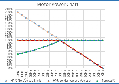
V/f Effects on Motor: With an Induction motor, as the frequency is reduced the voltage is reduced giving consistent torque with dropping Horse Power and as the frequency is increased and the voltage reaches maximum nameplate rating the HP remains consistent with the torque diminishing. As a VFD system is set up the output voltage is usually limited to its input supply. So a 480V powered VFD full available output would be under 480V. While in theory the voltage could go higher than the nameplate voltage for higher frequencies. In actual applications that would make the motor produce more HP than its rating and subject the windings to voltage higher than were designed to withstand. Over powering your motor can cause thermal and electrical insulation breakdown.

Motor selection Considerations: Induction motors are at their optimum at its rated nameplate voltage and frequency (60Hz). How much torque is required at the desired speed for the application is the next consideration. Just selecting a larger HP motor with larger drive to meet the varying power requirements may seem the simplest solution. It will cost more in components and efficiency. It is better to match the Motor speed for the application. Notice that for Variable Torque applications under speed Torque remains constant and for Constant Torque applications over speed Horse Power remains constant. To calculate HP [Horsepower = (Foot/Pounds × RPM) ÷ 5,252] or for you new schoolers (Pound-feet). Induction motors can be constructed with multiples of poles that will determine rotation speed for the nameplate frequency (60Hz). Check the motor manufacture for the maximum speed. For most Induction motors 3600RPM would be the typical maximum acceptable speed internal components could withstand. Use Inverter duty rated motors. Always consult with the motor manufacture for Maximum ratings.


