EZRack PLC Weigh Belt Feeder
by Paul Figie, Application Engineer, EZAutomation
By placing load cells on the supporting portion of the conveyor belt and controlling the belt speed we accurately calculate delivery weight product being dispensed. The VFD controlling the feed Auger determines the feed rate (lbs. /Minute)
 Requirements:
- EZRack PLC
- EZTouch HMI
- High Speed Counter Input (Belt Speed)
- 2 Analog Output (VFD controlled belt & feed auger)
- 1 Analog Input (from Load Cell)
Theory of operation:
By continuously weighing the material traveling across a section of a conveyor at a known speed the amount of weight that passes through can be measured along with the flow rate at any given point in time. The load cell output and the speed sensor signals are sent to the PLC where they are scaled and formulated to give the proper values to be used.
Weigh Bridge:
This is the section of conveyor that will use a load cell to “weigh” that section of belt with material on it. It is important to remember and factor in things that will affect the weighing process. It is important that the belt flexes to allow pressure to be exerted on the load cell. Here are things to consider: Flat is better than a Troughed belt. The trough shape in the belt will make it more rigid. There is more tension at the end of a loaded belt verses the beginning, so close to the infeed is ideal but remember the area that material is falling on the belt will not produce a true reading. The material must be settled on the belt before entering the weigh bridge area. The belt tensioning method used will factor in the scaling and calibration. Gravity tension & Spring tension methods can be used to get more consistent results. Belt stretch and belt alignment should be monitored to keep the calibration.
Speed Sensor
The speed sensor is used as the multiplier in the measurement equation so an accurate feed speed can be achieved. Example; Feet per minute x LBS per Foot = LBS per Minute. If the speed sensor is connected to the drive motor shaft and the belt has slippage you are not going to have good results. Consideration in the speed sensor position and technique should be well thought out. Always use a ramp up and ramp down in a manner that will not cause the material you are trying to measure to slide as the conveyor is started or stopped this too will give an inaccurate measurement.
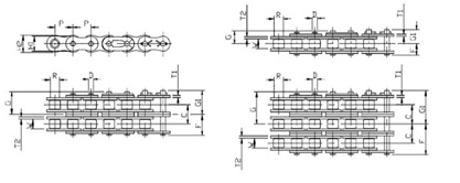
After the load cell and idler rollers have been properly aligned to be level and straight, belt tracking and tensioning will begin. There are different methods to setting up and calibrating the Weigh Bridge. I am going to share my preferred method. First the speed sensor is calculated to give the desired units. In our example I am using Feet per Minute. Now I will start with the desired weight per foot to be on the conveyor during operation. In this case it will be 2.5Lbs. With an unloaded belt the Load cell is tared to 0. Next I place a length of #120H roller chain across the Weigh bridge section with the ends each extending to the no weighing portions of the conveyor. Roller chain is flexible and its weight in a given length is consistent. The #120H roller chain has a 4.00Lbs per foot weight this will allow me to calibrate the load cell now to the extreme upper range. Next; I will use a length of #100 standard roller chain its weight is 2.54Lbs per foot. I try to select the Lbs. /FT to be as close to what the normal rate is to be measured. The EZRack PLC has a scaling functions that work well for accomplishing this kind of task. This will get the Weigh Belt Feeder ready for the final calibration that will be running a known weight batch through and make final adjustments as necessary.
Setup and Calibration
| ANSI Standard
|
Weight per foot | ANSI Standard | Weight per foot | ANSI Standard
|
Weight per foot
|
||
| 35 | 0,24 | 69-2 | 1.93 | 100-2 | 5.53 | ||
| 40 | 0.42 | 50.3 | 2.05 | 120-2 | 7.53 | ||
| 35-2
|
0.42 | 100 | 2.54 | 140-2
|
9.85 | ||
| 50
|
0.71
|
60-3
|
3.02 | 200 | 10.49 | ||
| 50H
|
0.75 | 80-2 | 3.39
|
140-3 | 15.00 | ||
| 40-2
|
0.82 | 120 | 3.73 | 200-2 | 21.23 | ||
| 60
|
0.97 | 120H | 4.00 | 240-2
|
32.52 | ||
| 50-2
|
1.34 | 140 | 4.83 | 240-3 | 48.19 | ||
| 80
|
1.68 | 80-3 | 5.10 | 240-4 | 63.00 |

By using the EZRack PLC to calculate & control and programming the EZTouch Panel with Tare and Calibration setups from the panel you get a professional first class system!


