Choosing a Sensor
by Paul Figie, Application Engineer, EZAutomation
Specialty Sensors come in a wide variety of functions that are capable of measuring Strain, Weight, Acceleration, Distance, Position, Pressure, Flow, Temperature, Power, Moisture, Color, and more. If there is something that needs to be sensed there is probably a sensor for it. The task is to get that sensor information to a device (PLC) that will in return control or monitor a process. When selecting any sensor it is best to match its measuring range to your process for the bet resolution.
Selecting Sensors with Analog Output
Many sensors have come to use industrial signal standards. Voltages 0 to 5Vdc, 1 to 5Vdc, 0 to 10Vdc, -10Vdc to +10Vdc and Current 4ma to 20ma are common. If the sensor is a long distance from the controller (PLC) the best choice would be the Current 4-20ma. The current loop is not affected by wire voltage drops and less susceptible to other voltage interference. Current loops also can provide broken wire detection in the case of zero current. These signals are scaled in proportion to the range of the sensing device. For an example a pressure sensor with a measuring range of 0 to 100psi would give corresponding signal for its output.
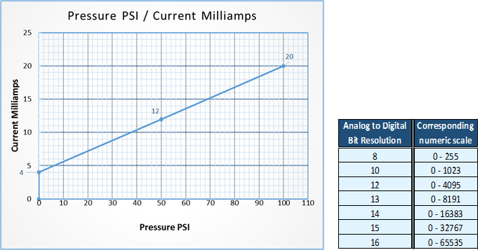
As the sensor inputs its signal to the Analog input module the signal is converted to a (Digital) numeric value that will correspond in range with bit resolution of the Analog to Digital converter. The sensor Analog signal inputted to the Controller (PLC) input register now is ready to be scaled and used. In the above example for the 0 – 100psi pressure sensor using a 12bit Analog module, simply divide 100 (sensor full scale) by Corresponding 12bit numeric scale 4095. This will be the scaling factor used to multiply the Analog input register to give an actual psi pressure value. Example the sensor measuring 50psi will send a 12ma signal. The input register value of 2048 multiplied by 100/4095 = 50. Follow the same formula with any Analog sensor in your controller and substitute the corresponding range & scale. Whether Flow, Weight, Pressure or whatever is being measured.
Thermocouple & RTD
Temperature Sensing is so common and necessary in control process that specialized input modules for RTD’s and modules for thermocouples are readily available.
RTD’s Change resistance with temperature and three of the most common types are Platinum, Nickel & Copper with Platinum being the most common and has the largest temperature range. RTD’s are very accurate and are generally good for temperatures up to 600 °C / 1100 °F. RTD’s response time is slower but they will be more consistent in calibration than thermocouples (do not have to check calibration as often)
Thermocouples are simple, rugged and inexpensive. Thermocouples are less sensitive than RTD’s and are good for temperatures up to 1820 °C / 3300 °F. Thermocouples use a dissimilar metal joint to create a Millivolt output signal. Thermocouples have a faster response time and can be made very small for tight spaces. Thermocouples are more prone to degrade with time depending on the environment of operation.
When choosing a temperature sensor it is best to select the range that will be the closest to your process to give the most resolution in your controller (PLC). I have included a quick chart with temperature ranges to help in selection.
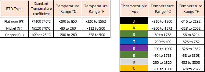
Sensors that do not have a standardized output will require an intermediate signal converting device that can add extra cost to your system. Make sure the PLC you select offers modules that will interface with the type of temperature sensor you need to use for your application. The EZRack PLC supports all of the RTD’s & Thermocouples in the above charts.


