Rotary Encoders - Taking the Mystery Out of Using Rotary Encoders
by Paul Figie, Application Engineer, EZAutomation
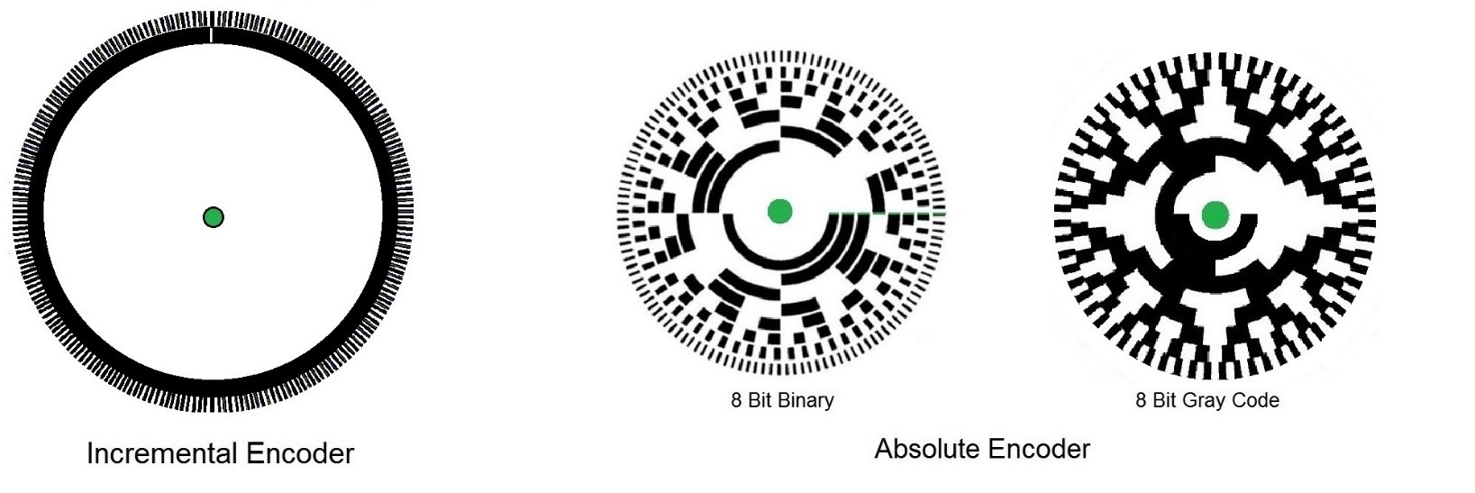
First let’s look at how they actually operate so we can have a better understanding of how to put rotary encoders to work. Two basic types of rotary encoders are Absolute & Incremental. Each has its attributes that make it ideal for specific uses. Rotary encoders read the position of a rotating disk usually optically or magnetically. The principle for each type of encoder is similar. By sensing patterns on a disk or wheel the position of the connected shaft is determined. For optical encoders, the marker is an opening which lets through light. For magnetic encoders, magnetic sensors are used to detect the markers on a disc in the same fashion. Below are some examples of what the optical discs inside an encoder may look like.

Absolute Encoders give a direct digital output for their position. They require multiple inputs for each Bit required to translate their position. They give a direct bit representation position by “reading” the Binary value associated its current position. The position is always available as long as power is applied, it does not need a home signal, and rotation while powered down will not affect position. They absolutely won’t lose position. The resolution of an absolute encoder is determined by the bit resolution. For example 8Bits = 256 so one revolution would give 256 positions. If a Higher resolution is required more Bits will be required and inputted to the controller. When the Binary form of the data changes with position the parallel data is inputted to the controller to interpret position. As encoder shaft Speeds increase the response time of the inputs and scan update of the controller must be capable to respond to the bit changes. This makes high Speeds with high resolution extremely difficult.
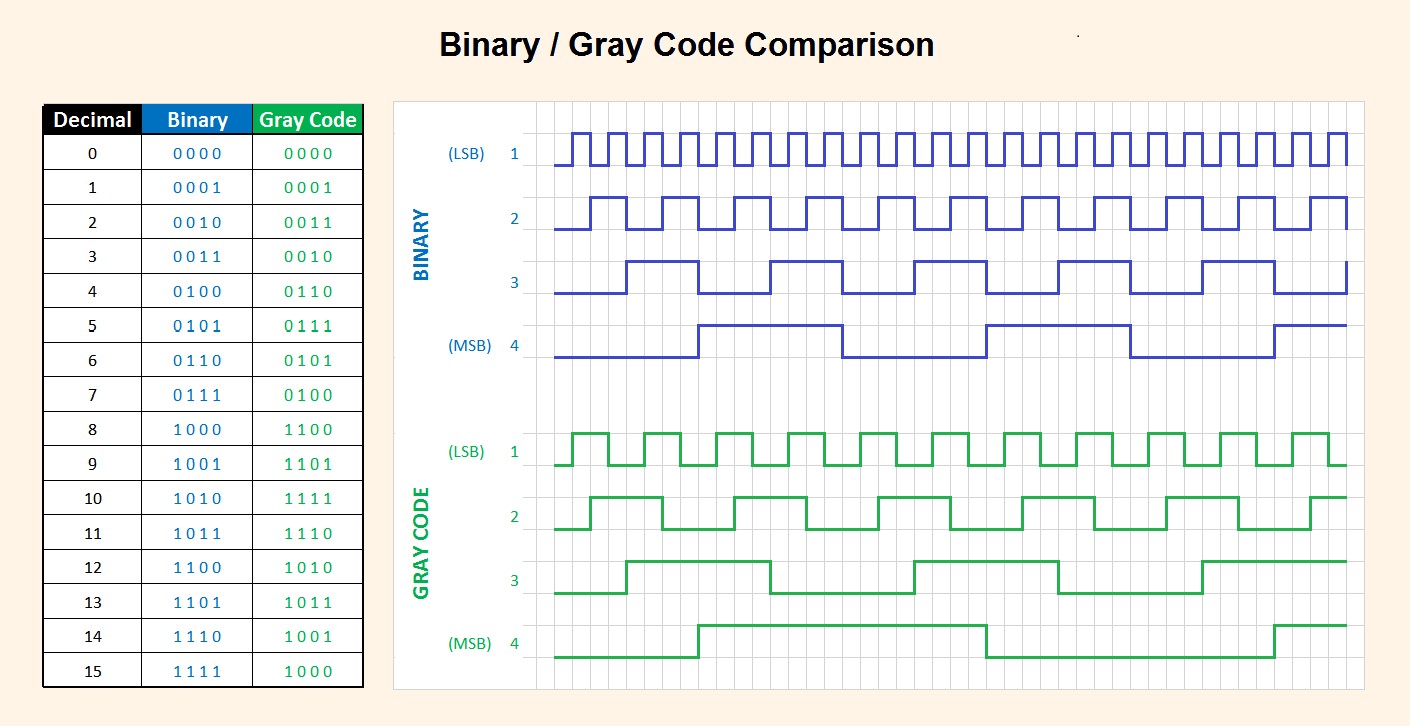
Binary Gray Code was developed to reduce the possibility of errors between large bit transitions. Gray code rearranges the bit order so that only a single bit changes for each incremental change. Observing the Binary/Gray Code comparison chart one can see that only 1 Bit changes per incremental change in the Gray code. Also note that the rate of change for the least significant bit (LSB) is ½ of change rate of the Standard Binary. This has proven to effectively reduce controller errors and allow shaft speeds to be increased significantly from standard Binary. In the EZ-PLC and EZ-Rack PLC a function is provided to do seamless Gray Code conversions.

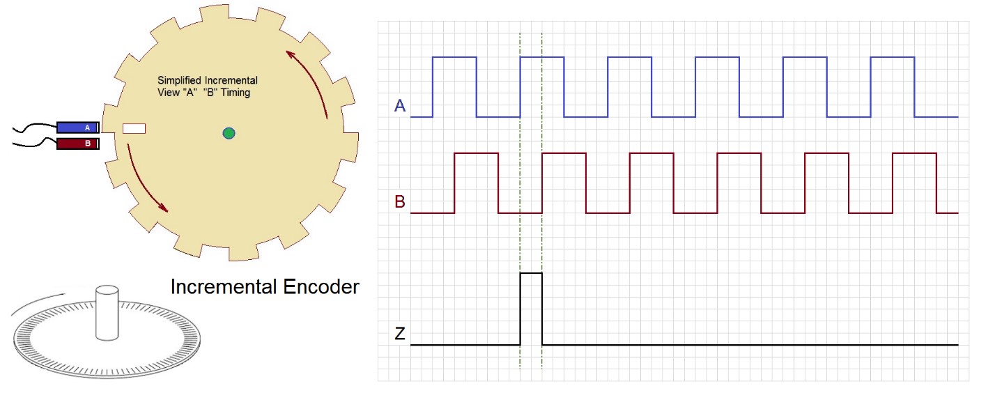
Incremental Encoders provide excellent speed and distance feedback and since there are few sensors involved, the systems are both simple and very cost effective. Incremental Encoders can provide extremely high position resolution with a minimum of required control inputs. The Incremental encoder sends pulses as it is rotated usually with a home or start signal. By using 2 Sensors placed at 90° phase of each other the direction is detected when “A” is “On” the “B” transition determines the direction by ether on or off state. Likewise “B” to “A”. Making the count increment or decrement for each change. This gives 4 distinctive positions for a single completed “A” cycle. This method is called Quadrature encoding. In the simplified Incremental example using 14 slots the total positions encoded would be 56 (4×14) using the Quadrature method. The design simplicity of Incremental encoders allow a wide range of achievable resolutions from 50 -5000 Pulses per revolution.

Incremental Encoders however are susceptible to a few factors. They will not maintain position if rotated under a loss of power. With Higher resolutions at high speeds they could lose position due to output/input frequency limitations. Incremental encoders only providing change information, so the encoder requires a reference device to store the motion information. Both Limitations are solved when a Dedicated High Speed Counter Module is added to your control. EZ Automations High Speed Counter Modules Take the guesswork out of Incremental encoders. Everything you need can be setup in the EZ High Speed Counter Modules configuration. Once the High Speed Counter is configured the all of the functions of the counts are continuously updated and stored in the PLC registers to be used in your control application.


